I spent the weekend starting on designing the robot. A few things have changed since I started the project. I’ve been trying to figure out how to feed the robot the images and finally decided on an idea. I’m going to write a python program that works as paint whilst remembering how the paths/drawing is drawn by logging the x-y coordinates of the lines. It’ll be a simple program that will output the x-y coordinates to an output file of some sort that will then be loaded onto the MCU.
I then went back and deliberated whether I needed the PSOC to be the MCU as it is probably overkill. I think I may switch to a teensy, but I haven’t quite decided yet.
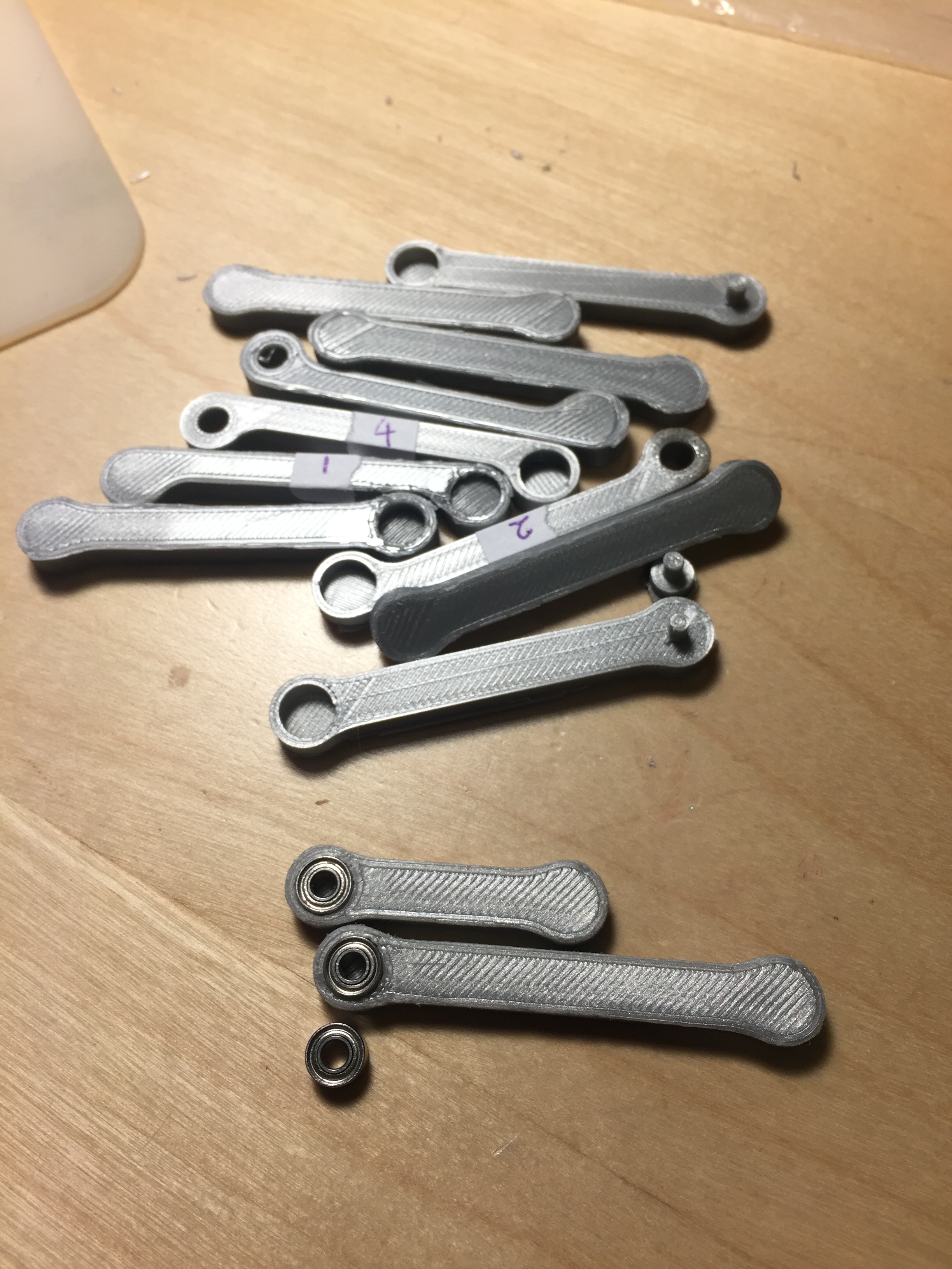
I also started designing the physical robot itself. I started with the arms as it was one of the more crucial parts of the project. I started by trying to print the gearheads of the servo into the arm with poor success. My 3D printer has a 0.4mm nozzle so getting the definition of the micro servo’s gears were difficult. I then decided to switch back to my original idea of using the servo arms and incorporating them as part of the robot arms. That worked out much better. I had real struggles with the tolerance on my 3d printer as I wanted the bearings to all have a press fit. I managed to get some and not on others. It was a real hit-or-miss for a while until I managed to calibrate my printer. Just shows that I need to be using that printer more often.
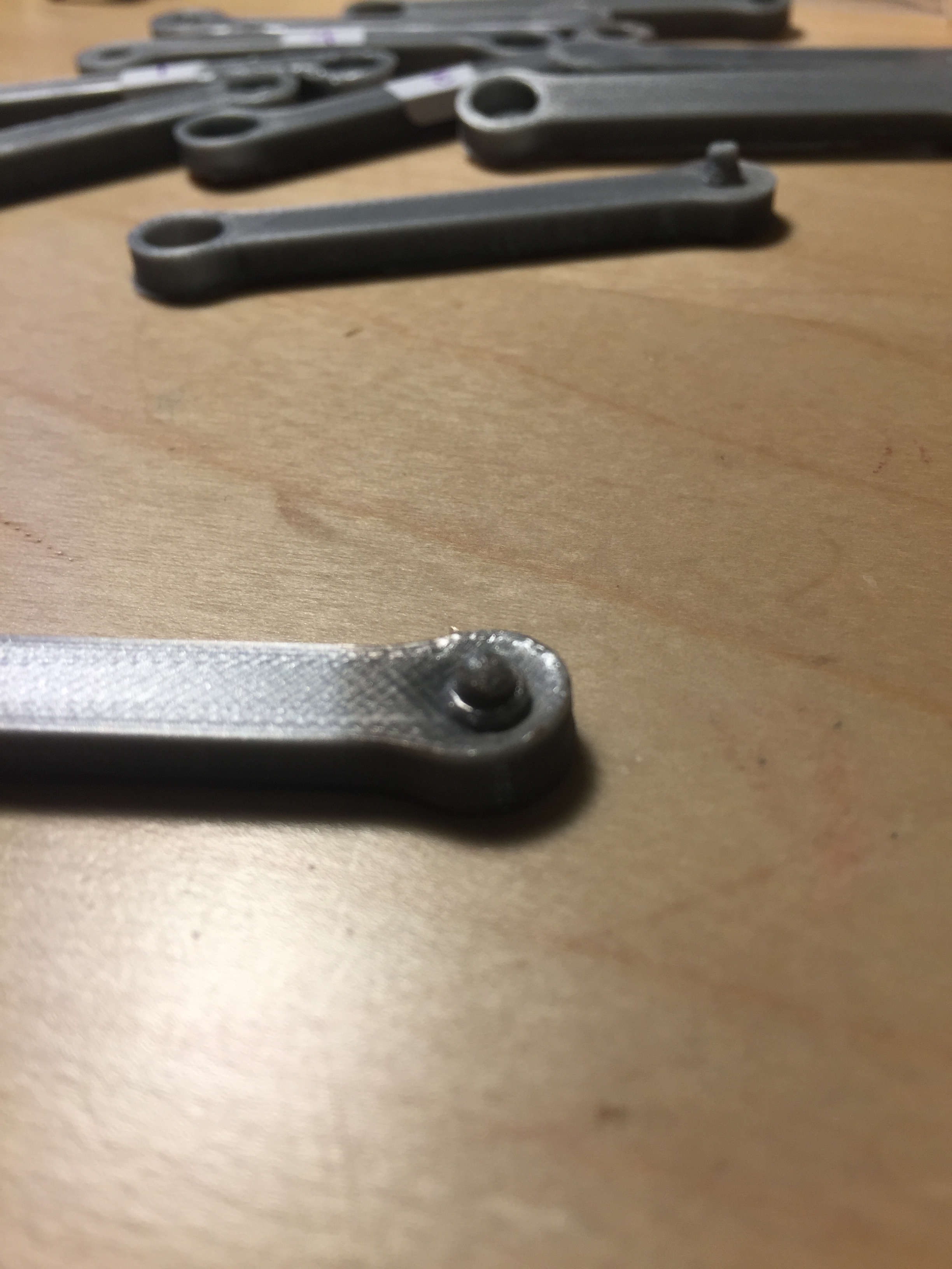
I had particular issues trying to get the pin for the middle of the bearing made. Because the bearing I’m using was so small (3mm x 3mm x 7mm – requiring a 3mm pin), the printer tended to overheat the print causing it to melt sadly as it grew. 
You can see the deformation at the base. This caused the bearings not to sit well on the arms. I tried reducing the size of the pin to compensate for that. Finally, by a stroke of luck, when I printed one of the prints at ulti-quality (printing it slower) it came out perfectly. I then figured that the nozzle was probably applying too much heat on that small surface area. I then decided to print a smaller test print of the same height a little away from that print so that the pin had time to cool after each layer.
Prior to figuring that out, I decided to heat one of the pieces with a lighter and smoosh a bearing on top in hopes that it would form to the bearing. It didn’t. I would not recommend this. Lessons were learnt
I also tried using glues and toothpicks to adhere the bearings to the plastic. Turns out hot glue does not stick to metal bearings well and elmer’s glue… well doesn’t work. It probably would have been easier to just screw everything together, but I was really aiming for that sleek look.
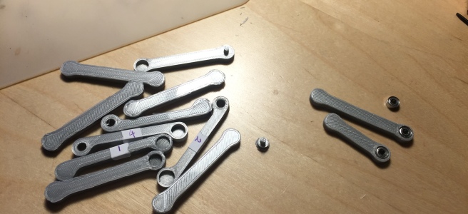
I finally figured out how to get the perfect prints after many many iterations. Here are some of the scraps with the 2 arms on the right actually being useable. There were more scraps that were lost during the prototyping process that aren’t in these pictures.

3D printing lessons were learnt this weekend, but overall I managed to get the arms all designed and mostly printed. I’m still tweaking the dimensions slightly to get an oh so much better fit. Unfortunately 3D printing is not like machining. I think I need to build more often as this tweaking took longer than it usually would have took me.

There are 3d printer joint/pin libraries for OpenSCAD on thingiverse.
http://www.thingiverse.com/thing:10541
LikeLike
Totally agree. I tried those but the gears were slipping.The micro servo’s gear heads were really small. I think there were limitations on the printer because the nozzle on the printer is 0.4 mm and the gears themselves were only a few mm. If I had a smaller noxzle it probably would have worked. I know I managed to do it on a makerbot a few years ago, but the ultimaker just didn’t agree.
LikeLike
Did you abandon the project? I would also try to replicate this project but I do not have enough skills myself. I was hoping in some person more expert than me.
LikeLike
Yes and no. I did make more progress than above. I actually finished building the robot but the torque given by the servos I had was not strong enough to actually press the pen down enough so that the ink showed on the paper. Mechanically the robot worked, but functionally it didn’t. And so I abandoned it at that point to start working on something else I had really wanted to do.
I haven’t been updating the project blog mainly because I realized I don’t really enjoy writing blogs. But please let me know if I can help.
LikeLike
Could you please share the cad files and the arduino code? However, I do not understand how the problem could be the servos. Are not these servos like “standard”? I believe that the ones Line-Us is using are the same servos you can find on AliExpress or Bangood.
LikeLike
I can share the cad files. I’ll have to look for the arduino code.
As for the servos, I used metal gear servos but I literally got the cheapest bulk ones off amazon. I didn’t think that the torque would have mattered at that time. Every servo has a certain torque it’s spec-ed to. It’s probably true that line-us’ servos are from those websites.
Note: the cad files would have included clearances specific to my 3D printer which is an ultimaker original +
LikeLike
Well, of course the best would be to write a last log with all the progress sharing as much as you can before you also forget some important details that comes with time. So share the cad files, the arduino circuit and the code. Maybe someone else can take the opportunity and terminate it. I really would like to accomplish this as a gift for a special person who likes to draw.
It would be such a pity to leave all your efforts undiscovered!
LikeLike
I sent you the CAD files directly already because wordpress doesn’t allow me to post the CAD files online. The file type is not supported.
I can try to post the other details online but honestly it’s been a while (I know it’s only been a few months, but I look at new circuits everyday for work so a lot of it gets jumbled up). Honestly, Barton Ding has made a fantastic log of how he built his Line-us Clone which works and he has plenty of resources that people can use to build their Line-us clones off.
Here is the link to his project logs: http://www.buildlog.net/blog/2017/02/a-line-us-clone/
He’s brought the project much further than I probably would have and I made a lot of my design choices based off his logs so that would probably be a great place to look for more help on the project.
Good luck on it!
LikeLike
Yes, I actually discovered your project through his logs. The fact is that Barton Ding only shared pictures and videos of his accomplishments and the cad files. He does not intend to share more. And with these you cannot do much as I am just a hobbyst. I am a chemist and I don’t have the abilities to reproduce the arduino code he wrote. For you is easier since you are “in the field”. But the beauty of arduino is that also people like me can build difficult things and then learn from the code.
LikeLike